
Items needed
- Adafruit Pi Cobbler
- HD4470 LCD Character Display
- A (https://www.sparkfun.com/products/245 or http://t.co/LGdx9Ewp – the one I used in this tutorial)
- 4.7kΩ resistor, a full size breadboard or two half size, and a selection of wires.
- A potentiometer (TRIMMER 10K OHM 0.5W TH) http://www.digikey.com/product-detail/en/3386F-1-103TLF/3386F-103TLF-ND/1232544?cur=USD
- Solder, heatshrink tubing, and a soldering iron.
- And of course, a Raspberry Pi
Assumptions
- The Adafruit Pi Cobbler has already been soldered. See http://learn.adafruit.com/adafruit-pi-cobbler-kit
- You have soldered pins to the bare wires of the DS18B20 temperature sensor (and covered with heatshrink) to allow them to be inserted into the breadboard.
We’ll be directly using 7 GPIO pins in total to connect the LCD character display and the 1-Wire temperature sensor directly to the Pi.
Wiring Diagram
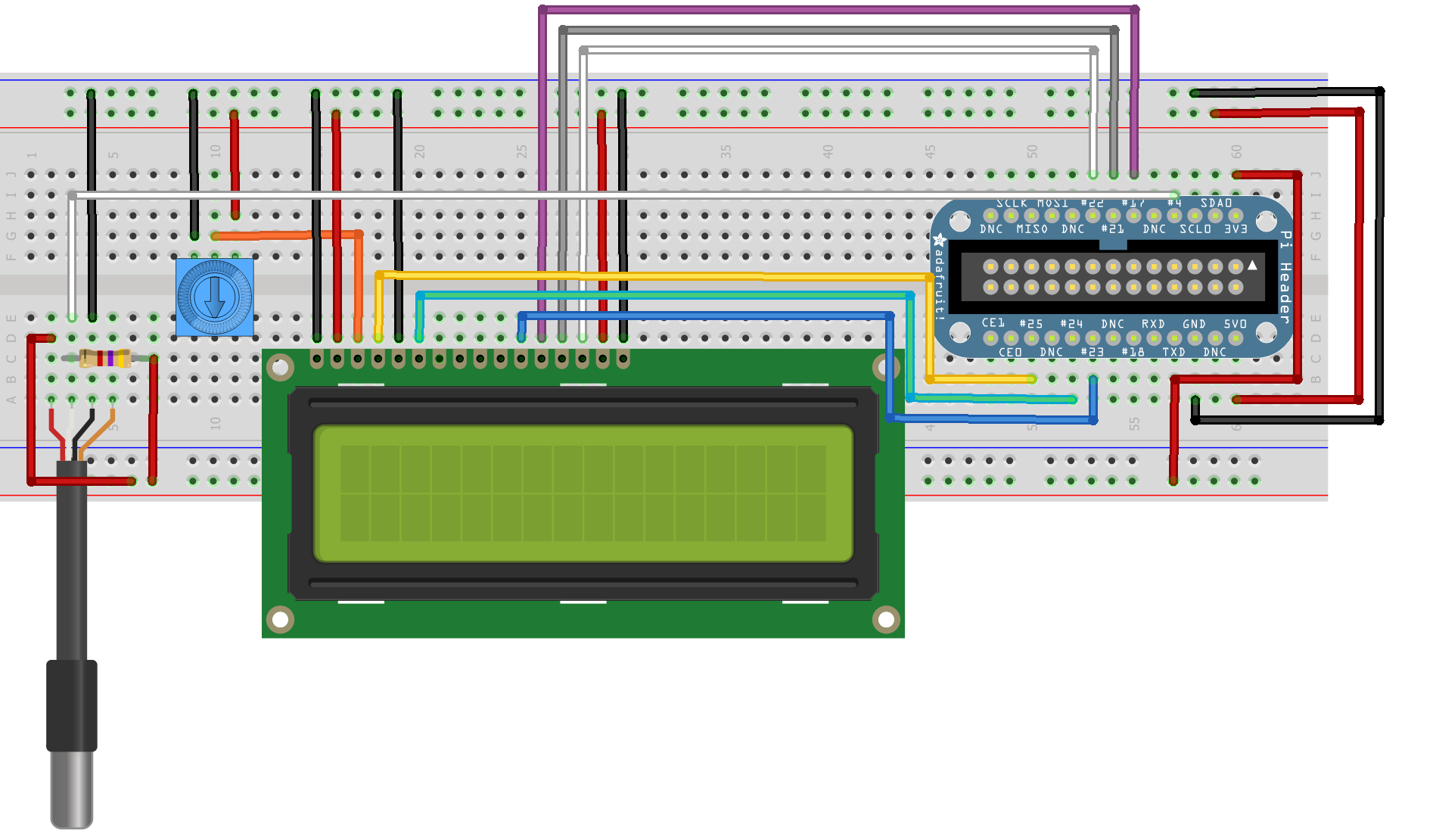
Connect the cobbler power pins to the breadboard power rail. +5.0V from the cobbler goes to the red striped rail (red wire) and GND from the cobbler goes to the blue striped rail (black wire)
In order to send data to the LCD wire it up like this
- Pin #1 of the LCD goes to ground (black wire)
- Pin #2 of the LCD goes to +5V (red wire)
- Pin #3 (Vo) connects to the middle of the potentiometer (orange wire)
- Pin #4 (RS) connects to the Cobbler #25 (yellow wire)
- Pin #5 (RW) goes to ground (black wire)
- Pin #6 (EN) connects to cobbler #24 (green wire)
- Skip LCD Pins #7, #8, #9 and #10
- Pin #11 (D4) connects to cobbler #23 (blue wire)
- Pin #12 (D5) connects to cobbler #17 (violet wire)
- Pin #13 (D6) connects to cobbler #21 (gray wire)
- Pin #14 (D7) connects to cobbler #22 (white wire)
- Pin #15 (LED +) goes to +5V (red wire)
- Pin #16 (LED -) goes to ground (black wire)
Then connect up the potentiometer, the left pin connects to ground (black wire) and the right pin connects to +5V (red wire)
Next, connect the cobbler +3.3V power pin to the breadboard bottom red striped rail (red wire). Then connect the DS18B20 temperature sensor as follows:
- Connect pin 3 on the sensor (red wire) to the 3.3V GPIO pin
- Connect pin 1 (black wire) to the ground GPIO pin
- Connect pin 2 (white or blue wire) to the GPIO pin 4
- Put the 4.7kΩ resistor between pin 2 and pin 3 of the temperature sensor.
- Ignore the 4th wire (if present)
- To test that the connections are the right way around, turn the Pi on, then put your finger against the sensor. If it is connected wrong, then it will get very hot within a second or two, in which case, turn the Pi off once it has booted and wait a while for it to cool down. Then take out the sensor and put it back in again the right way round.
Software Packages
LCD Screen
This guide is based on Debian’s “Wheezy” release for Raspberry Pi.
Add the latest dev packages for Python
$ sudo apt-get install python-dev
Upgrade distribute (required for RPi.GPIO 0.3.1a)
$ sudo apt-get install python-setuptools
$ sudo easy_install -U distribute
$ sudo apt-get install python-pip
Install rpi.gpio (0.3.1a) or later
$ sudo pip install rpi.gpio
I used the Python code for Adafruit’s Character LCDs on the Pi and it is available on Github at https://github.com/adafruit/Adafruit-Raspberry-Pi-Python-Code
$ git clone https://github.com/adafruit/Adafruit-Raspberry-Pi-Python-Code.git
$ cd Adafruit-Raspberry-Pi-Python-Code
$ cd Adafruit_CharLCD
You can test the wiring from the previous step by simply running the Adafruit_CharLCD.py python code, as it has a little code it in that will simply display a test message when wired correctly
$ sudo ./Adafruit_CharLCD.py
Temperature Sensor
$ sudo modprobe w1-gpio
$ sudo modprobe w1-therm
$ cd /sys/bus/w1/devices/
$ ls
In the listing you will see one with a load of numbers, this is the serial number of the sensor. ie. 123-123456789
$ cd 123-123456789
$ cat w1_slave
You will see two lines of text outputted. The second line has the celcius temperature, its the number after the “t=”. Divide it by 1000 to get the actual temperature two digits, so the example value of “t=18750″ is actually “t=18.750″ Celsius
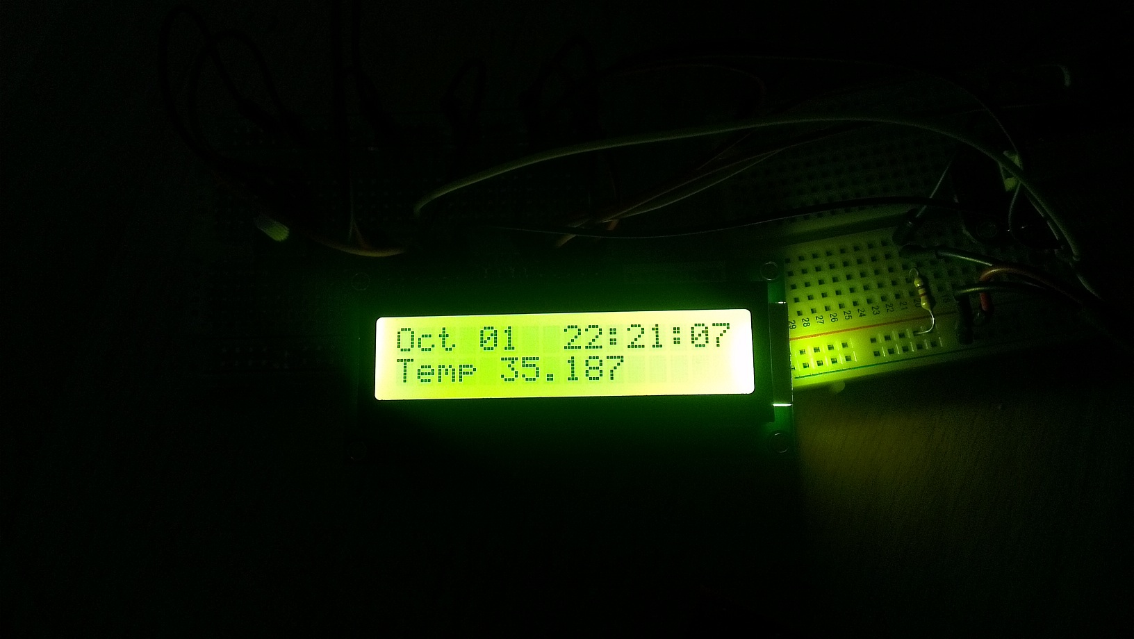
Combining the Two
$ cd Adafruit-Raspberry-Pi-Python-Code
$ cd Adafruit_CharLCD
$ vi CharLCD_Temp.py
|
|
Save and run the script:
$ sudo ./CharLCD_Temp.py
Et Viola
This post was inspired by the following tutorials:
http://www.cl.cam.ac.uk/freshers/raspberrypi/tutorials/temperature/
http://learn.adafruit.com/drive-a-16×2-lcd-directly-with-a-raspberry-pi/overview